


TL;DR
- Rockchip has a structured sequence of bootloaders.
- Using various plugs can allow access to the MCU’s RAM and storage.
- There are many utilities to allow reading of information from the MCU.
- Use this guide to access and reverse engineer bootloaders.
Introduction
Rockchip are a Chinese company that makes a number of devices, including tablets and single board computers (SBC). They first came to prominence producing Micro Controller Units (MCU) designed for MP3 players in the days before smart phones.
We have talked about accessing Rockchip’s bootloader in the past with reference to many cheap tablets, such as the Tesco Hudl, Argos MyTablet and the Aldi Lifetab. All of these used the firmware’s common USB interface and the rkflashtools project.
I wanted to expand on this information as details are sparse around the Internet with little snippets being found on different websites or in different tools with different names and information. Rockchip, like a lot of large Chinese companies also put most of their datasheets under NDA, meaning that it can be difficult to legally find information out.
Boot Process
When a Rockchip MCU initially boots it will load the primary program loader, known as PPL or BootRom, from its internal EPROM. This is static code and cannot be changed.
The PPL will then connect to flash or eMMC to load the Secondary Program Loader, known as SPL or idbloader. As SPL is stored on flash, this can be updated. There are variants of SPL, depending on whether SPL process is based on U-Boot or raw executables, known as miniloader.
If no flash or eMMC can be found then PPL will drop into a special mode, known as MaskROM, more on this later.
SPL will continue the boot process, by loading a bootloader, usually this will be a standard operating system bootloader such as U-Boot or Android’s ABL. The bootloader will control the initialisation of and trust modules and then boot any operating system as normal.
There are opportunities to interact with each level of the boot process, which can be used to attempt to gain control of a device or to manipulate flash.
The Rockchip Wiki has a good page on the boot process.
MaskROM Mode
As stated above, if PPL cannot find anywhere to load SPL from then it will go into MaskROM mode. This can be due to a corrupt or blank flash chip, an SD-Card being ejected or by shorting pins on the flash chip. Some SBCs may also have a button or pads that can be shorted to force MaskROM mode.
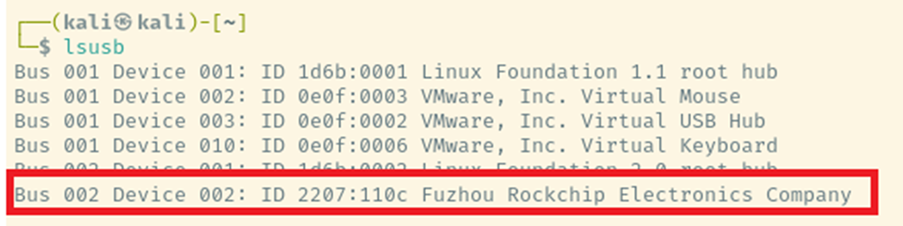
MaskROM shows up as a USB device with an ID of 2207:????. The device has one configuration with one interface and two interfaces (0x02 and 0x81) for bidirectional traffic. The Interface is of a custom class.
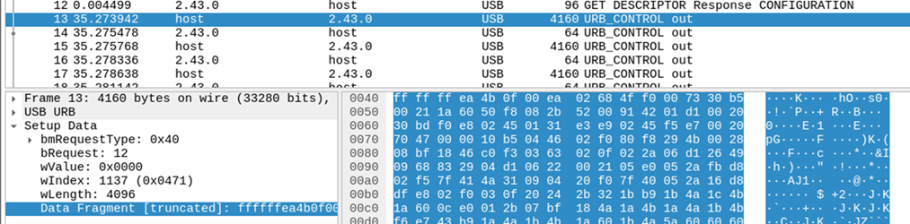
All this interface allows is the uploading of raw ARM code via URB_CONTROL requests. USBPcap allows the sniffing of USB conversations showing where the update happens.
To have access to the flash or the bootloader, two binaries are usually uploaded, ddrplug, which defines the RAM configuration. This is usually specific to the MCU and can usually be obtained from RockChip; copies of which can be found on the Internet. Unfortunately there’s no easy public access to these, although copies can be found from OEM vendors. The plugs are only loaded into RAM and will not brick the device if the wrong plug is used.
After ddrplug is uploaded the next stage, usbplug, can be uploaded through the same mechanism as ddrplug. This loads into RAM at address 0x00000000 and controls the basic bootloader USB protocol. Once this is uploaded it is executed and replaces the PPL interface.
Usbplug allows the use of the rockusb communication protocol over USB. The protocol is quite simple and there are a number of tools that can support it, including xrock, rkflashtool and the formal RockChip tools.
To get a MCU in MaskROM mode to start communicating through rockusb, the xrock tool can be use, for example:
xrock maskrom ../rv1106_ddr_924MHz_v1.15.bin ../rv1106_usbplug_v1.09.bin
Rockusb Mode
This is the basic protocol that allows low level communication with the MCU over USB. The protocol allows a number of directives that can do various different actions, including writing to flash and reading MCU stored data, such as serial numbers.
It can be accessed by using MaskROM and uploading the expected plugs, or, if the miniloader is used, there’s usually a combination button press that can be used to get into the mode. This has been described a few times in different articles, but is dependent on the MCU and the miniloader in use.
It can also allow the execution of custom code or dumping of RAM. It’s generally quite useful all around!
The protocol is generally easy. It looks a bit like USB mass storage until you dig into it a bit further and realise it’s all based on custom packets. The rkflashtool project describes the basics of the protocol on its GitHub page. The commands can be extracted from the public sources, reverse engineered or fuzzed.
Of course you could always sniff it using USBpcap, and here’s a screenshot of one I made earlier:
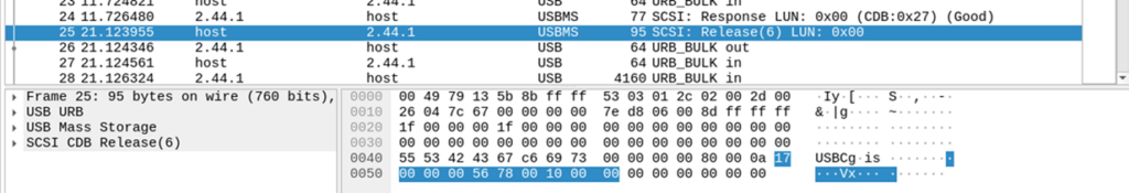
With the URB payload in this base being to read SDRAM from 0x5678 for 0x100000 octets:
| Bytes | Use |
| 55 53 42 43 | USB mass storage signature: “USBC” |
| 67 c6 69 73 | Randomly generated tag |
| 00 00 00 00 | Data transfer length |
| 80 | USB direction – in this case host to device |
| 00 | LUN – usually 0 |
| 0a | Command length |
| 17 00 | Opcode (READ_SDRAM) |
| 00 00 56 78 | Address (0x00005678) |
| 00 10 00 00 | Length (0x00100000) |
Reverse Engineering the Firmware
If we can extract the plugs we can load the firmware into your favourite reverse engineering tool (in this case Ghidra). In the below screenshots I’m looking at the ddrplug and usbplug for the RV1106 (a dual ARM and RISC-V MCU, which is quite funky).
The main MCU uses the ARM core, in 32-bit ARM mode. Although the memory map is on a datasheet covered under NDA, we can use the read SD-RAM opcode it is possible to identify that the base code loads into address 0x00000000.
Ddrplug just sets up RAM, so I’m not too interested in that so we can just look at usbplug. I’ve changed function and label names to what I think the function is called, which may or may not be exact.
Starting is simple: analyse the firmware and find the USB signatures: USBC and USBS as these will be static and will lead to the USB packet parsing code:

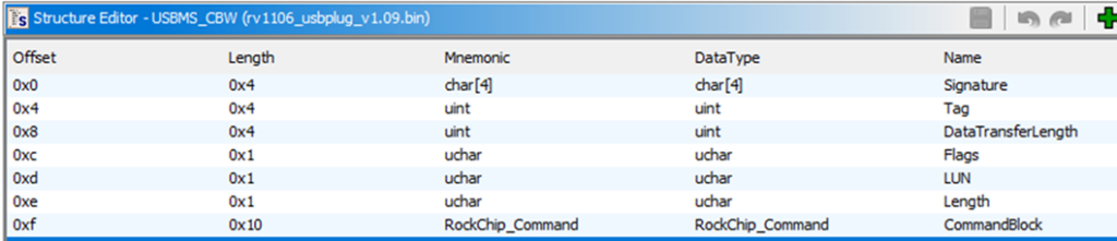
Which leads to a function to check the packet’s signature. Note that USB_InputBuffer is a static address, which can be defined as a structure within Ghidra.
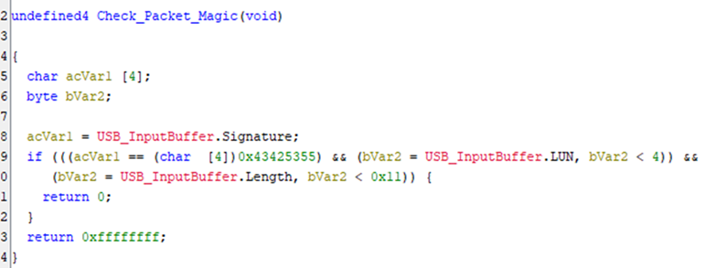
Finding what references Check_Packet_Magic allows us to identify the function used to parse the USB Packet, which uses a massive switch statement on the opcode:
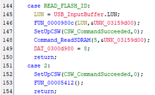
Further reverse engineering is left as an exercise to the reader.
Tools
There are plenty of tools that talk both to MaskROM and the rockusb protocol, some of these are official rockchip tools, some are reverse engineered and open source.
xrock
Found at https://github.com/xboot/xrock.
This is my current favourite tool as it shows better how the process works and has the most exact implementation of the rockusb protocol. It has shortcuts to the most common commands and some nifty ARM32 shims that can upload custom code and allow different tasks to be performed.
rkflashtool
Found at https://github.com/linux-rockchip/rkflashtool
I used to use this tool for it is perfectly valid. It transparently handles MaskROM uploads and has a relatively simple mechanism for interacting with rockusb.
rkdeveloptool
Found at: https://github.com/rockchip-linux/rkdeveloptool
Like all open source projects, why have one, when you can have 3? This is a clone of the official upgrade_tool which provides a similar interface. It’s not well documented and the interface really isn’t very nice, so I would avoid.
upgrade_tool
A copy can be found at: https://github.com/vicharak-in/Linux_Upgrade_Tool
This is an official Rockchip tool for Linux, which is closed source. It uses preset binaries which contain the ddrplug, usbplug and miniloader in one package. The interface isn’t very nice, so I would use the open source tools in preference.
SocToolkit
A copy can be found at https://github.com/LuckfoxTECH/luckfox-pico/blob/main/tools/linux/SocToolKit/SocToolKit
This is a Windows GUI version of upgrade_tool.
Conclusion
This was a short look at how one manufacturer’s MCU boots, its low-level communication protocols and some utilities to talk directly to the bootloader.
The protocols are interesting from a technical viewpoint, and are similar to other MCU manufacturer’s but do not imply any massive security risk. At the worst case, data could be extracted from RAM, or from any unencrypted volume.
In the past, before Android had disk or file encryption, this protocol had been used to extract data from tablets.


No Comments yet!