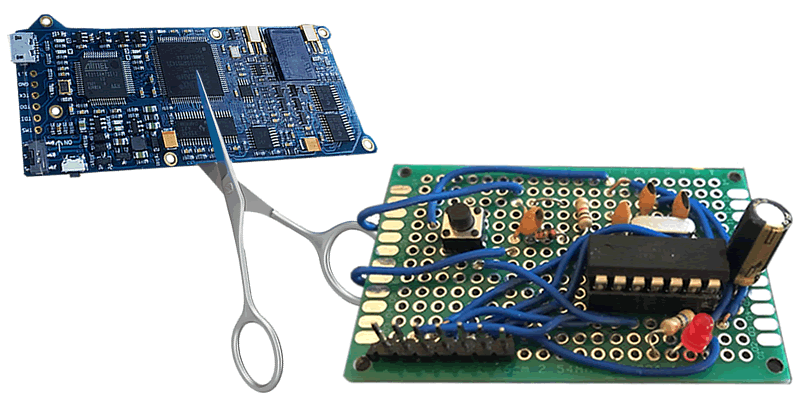
The Proxmark is an awesome device – we have a few here. However, it’s quite expensive for the NFC hobbyist.
Clone-ish devices are available for rather less, but if you have some soldering skills, here’s how to build an NFC tag emulator device for around $10 of components.
Along the way we’ll show how we reverse engineered the protocol that that makes up the construction of the ISO-14443A standard, to see where there were exploitable weaknesses. We created a device that was capable of emulating Mifare tags, which are often seen to be black boxes with rigid and obscure access controls, despite the known weaknesses in their encryption. I intended to find weaknesses outside of the encryption layers as these are completely wide open.
Equipment used
For this project, I decided to try to develop the device without using any traditional debugging equipment for this kind of platform. This would have included a traditional USB NFC reader such as the following:
…or tools geared more towards security professionals such as the Proxmark3 or Chameleon Mini:
During development I did find a similar project using similar hardware which could have been adapted, however I wanted to design mine from scratch, though it did have some good pointers:
http://blog.nonan.net/2013/11/simple-nfc.html
The reason for this being that, while these tools are certainly far superior in functionality, and are easily modifiable for a user’s own ends, using one would not provide me the same insight as developing a similar device myself.
The key equipment used for debugging this project ended up being my Hobby Components Logic Analyser and my RTL-SDR. For programming and development, I used my Arduino in order to program the ATTiny84 that became the centre of the project, and my STM32f401re development board for debugging (why this was necessary will be explained later).
Debugging tools created
During the development, it was found that analysis of the commands from the reader would be required from an out-of-band channel. Direct access to this information was not possible from the reader itself, as it’s USB implementation was set up purely as a HID device, with limited access to the NFC hardware on the device. I decided the best option for gaining access to the necessary information would be to use my trusty RTL-SDR. This device has, in the past, proven to be capable of viewing NFC packets, and as such I felt it would be possible to create an application to do this.
Initially, I took an older project of mine, that allows a user to view SDR IQ samples, and their amplitude, and analyse them with traditional logic analysing software:
The first thing to note about this project is that a standard RTL-SDR is incapable of tuning to the same frequency that an NFC reader uses, that being 13.56Mhz. However, it is more than capable of tuning to one of its harmonic frequencies, 27.12Mhz. Tuning to this frequency and running it through the analyser application revealed that the transmission from the reader was easily viewable with a standard, and therefore it would be simple to write an application to decode this for analysis. Unfortunately, responses from the tag would not be viewable, due to the transmission and modulation schemes used (more on that later). Taking this information, I created an application which sampled at the frequency 27.12Mhz with a sample rate of 1.695Mhz (this sample rate was chosen because it is within the allowed sample rate range of the RTL-SDR and is also a multiple of the data rate of the reader). Taking the data outputted from this, I could parse commands from the reader in order to view them for debugging, culminating in the creation of this small tool:
Unfortunately, due to this tool only being capable of analysing commands from the reader, and not the tag, there were still problems with debugging later, especially when debugging the encryption layer. These were mitigated by using a Logic Analyser to keep track of commands and responses.
The hardware
I decided to use an ATTiny84 as the core MCU for the device, as it could easily use external clocks, had a decent amount of program space, and also had onboard EEPROM. To work at the correct frequency I used a 13.56Mhz crystal, with the appropriate capacitors to match it, and for receiving commands from the reader, I used a Resonant Inductive Coupler:
…fed into an Envelope Detector:
This was then attached to a GPIO input pin for receiving the signal.
There was one key weakness with using this chip, and that was that the pins for the external crystal were the same pins used by the UART. Due to the fact that the Arduino I had configured as an ISP Programmer was incapable of debugging via any other methods, I had to clock out any debugging strings over different pins to an STM32f401re board, which converted this to UART, as software based UART at these frequencies was too inconsistent.
For power and mitigation against noise, an Electolytic Capacitor and A SuperCapacitor were added between the power and ground pins.
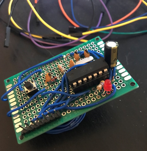
This was then put together into the following prototype board:
The protocol
The low level NFC protocol is very simple. Two different coding schemes are used by the reader and the tag to communicate.
The reader uses an coding scheme called Modified Miller, defined as follows:
- 0 bit after 0 bit: low for the first quarter of the transmission, followed by high for the remainder of the transmission
- 1 bit: high for the first half of the transmission, followed by low for one quarter of the transmission, and high for the remainder of the transmission
- 1 bit after 1 bit: high for the entire transmission
An example of the coding used to send a command is as follows:

When a reader communicates with a tag, it drops the power it is supplying to the tag to communicate. This coding scheme is specifically designed so that the tag has enough remaining power to process the transaction while the power is being disabled.
Tags use a more traditional radio communication coding, Manchester Coding.
This protocol uses either a high to a low setting to encode a 1, or a low to a high for a 0. In order to communicate using this protocol it uses what is known as “Load Modulation”. This modulates a signal in order to create resistance in the power being sent to the tag, which the reader can interpret as the response.

For more information on these coding schemes, view the following link: http://www.radio-electronics.com/info/wireless/nfc/near-field-communications-modulation-rf-signal-interface.php.
Packets are constructed using a start of frame bit, followed by a byte of the frame, and a parity bit, based on the number of set and unset bits in the byte. Bytes are sent in order, and bits are sent lowest significant bit first, for example, the following command:
0x26 – REQA:
Bits Sent: 0 0 1 1 0 0 1 0 0
The above command is the REQA command, used to request that any tags new to the reader respond.
Commands are sent and responded to by the tag in order to process through the state machine used to communicate between the two devices:
RD: 26 - REQA
TG: 0f 01 - ATQA
RD: 93 20 - SELECT1
TG: 04 ac e9 b2 f3 - UID
RD: 93 70 04 ac e9 b2 f3 f0 98 - SELECT
TG: 08 - ACK
RD: 50 00 57 cd – HALT
Implementing the protocol
Implementing the protocol on the ATTiny took a few iterations due to a number of issues, the most key of which being clock drift. ATTinies in general have a big problem with clock drift, and therefore my initial attempted to implement the protocol using purely the clock and intervals in order to receive a bitmask for the transmitted modified miller bits, IE:
0b0111 – 0 after 0
0b1101 – 1
0b1111 – 0 after 1
Was found to only get the complete transaction around 60% of the time. This would be inadequate, as the reader would be constantly believing that the tag is being removed and reintroduced to the field.
Due to this, timers were used in conjunction with GPIO interrupts, checking the time between each time the pin was set low, allowing for a sufficient amount of clock drift while still getting the complete transaction.
Communicating back was done by attaching an additional GPIO pin to the receive pin, and using PWM on that pin in order to increase the load and perform the load modulation. This was found to work well, though it could cause issues on certain readers if the voltage being used by the chip was too high.
The encryption
As I was aiming to emulate Mifare Classic Tags specifically, I had to implement the Crypto-1 encryption algorithm. This algorithm is well known for being weak and has been broken several times, but full implementation of it was necessary. For reference, I used the definitions found on the Wikipedia page: https://en.wikipedia.org/wiki/Crypto-1 as well as the well known “Crapto1” library built into the Mifare Classic Universal Toolkit: https://github.com/nfc-tools/mfcuk.
Writing a similar implementation of these functions was easy, however there were some key shortcomings that meant that large portions had to be rewritten. The most key of these being that Crypto-1 is based on 32-bit arithmetic and therefore any operations performed on the ATTiny’s 8-bit Microcontroller would take up to four times longer. In addition to this, the ATTiny lacks a method of bit shifting more than one bit at a time, this means that it is poorly suited for handling the majority of encryption algorithms, as they often rely heavily on bit shifting. These weaknesses meant that the device was too slow to respond to encrypted commands and therefore would get out of sync with the reader. In order to mitigate against this, I decided to optimise my implementation and rewrite it into AVR Assembly.
The function that was found to be eating up the most amount of time was the filter function. This function has the most complex calculations being performed, and due to its nature requires manual optimisation. The following example of the function being implemented was pulled from the Crapto-1 library:
int filter(uint32_t const x)
{
uint32_t f;
f  = 0xf22c0 >> (x       & 0xf) & 16;
f |= 0x6c9c0 >> (x >>  4 & 0xf) &  8;
f |= 0x3c8b0 >> (x >>  8 & 0xf) &  4;
f |= 0x1e458 >> (x >> 12 & 0xf) &  2;
f |= 0x0d938 >> (x >> 16 & 0xf) &  1;
return BIT(0xEC57E80A, f);
}
Some important points can be made about how this function has been implemented:
- Five 24-bit constants are used for bit shifting, however these are actually only two different constants, bit shifted to optimise some calculations.
- The x value is being bitshifted in line with the rest of the functions, despite being able to bit shift 4 bits at a time as the function is processed.
- Each value set by each line corresponds to a specific level of bitshifting, and as such could be handled independently.
Each of these points have their own methods of optimisation due to this.
- The use of 24-bit constants means that converting to assembly and handling the arithmetic as 24-bit rather than 32-bit means we already save a quarter of our calculation time for these functions. In addition to this,
- Bit shifting the value x by 4 bits outside of each line will save more cycles. In assembly, I ended up setting each masked value from x into each register, as this saved a lot of bit shifting.
- Each line can be optimised in a different way to emulate looped bit shifts.
The final point was the most key to reducing the amount of cycles used for the calculations. Taking each line independently and performing different calculations save a huge amount of time. The following was done for each bit shift:
- 16 bit – copying the two upper registers for the constant value to the lower two registers
- 8 bit – copying the second lowest byte’s value to the lowest byte
- 4 bit – using the AVR SWAP command to swap nybbles
- 2 bit – two traditional bit shifts
- 1 bit – one traditional bit shift
Performing these optimisations created this nasty bit of assembly:
cryptoFilterAsm: ; sped up filter function for crypto1
push r18
push r17 ; push registers we want to use
push r16
mov r21, r22 ; set up each shift value into register
andi r22, 0xf
mov r20, r23
andi r23, 0xf
andi r24, 0xf
swap r21
andi r21, 0x0f
swap r20
andi r20, 0x0f
ldi r17, 0x0a ; set shift constant 0xEC57E80A - not using reserved registers to save push and pop cycles hence the weird choices
ldi r16, 0xe8
ldi r27, 0x57
ldi r26, 0xec
ldi ZH, hi8(firstLookupTable) ; set up first space for lookup
ldi ZL, lo8(firstLookupTable)
add ZL, r22
adc ZH, r1
lpm r22, Z
cpi r22, 0
breq endShiftSixteenBit
mov r16, r26 ; this will shift 16 bits in two operations rather than the ton it usually takes
mov r17, r27
endShiftSixteenBit:
ldi ZH, hi8(secondLookupTable) ; set up first space for lookup
ldi ZL, lo8(secondLookupTable)
add ZL, r21
adc ZH, r1
lpm r21, Z
cpi r21, 0
breq endShiftEightBit
mov r17, r16
endShiftEightBit:
ldi ZH, hi8(firstLookupTable) ; set up first space for lookup
ldi ZL, lo8(firstLookupTable)
add ZL, r23
adc ZH, r1
lpm r23, Z
cpi r23, 0
breq endShiftFourBit
swap r17
andi r17, 0x0f ; may not be necessary
endShiftFourBit:
ldi ZH, hi8(firstLookupTable)
ldi ZL, lo8(firstLookupTable)
add ZL, r20
adc ZH, r1
lpm r20, Z
cpi r20, 0 ; if its zero, skip
breq endShiftTwoBit
lsr r17
lsr r17
endShiftTwoBit:
ldi ZH, hi8(secondLookupTable)
ldi ZL, lo8(secondLookupTable)
add ZL, r24
adc ZH, r1
lpm r24, Z
cpi r24, 0
breq endShiftOneBit
lsr r17
endShiftOneBit:
andi r17, 0x01
mov r24, r17
pop r16
pop r17
pop r18
ret
Optimising this functionality managed to make the encryption functions run 10 times faster than the original implementation, and allowed for the commands and responses to be encrypted in enough time for the reader to receive them.
Interesting features – Emulating multiple tags
I’ve been working on adding a feature that I’ve not seen on any other devices, including the Proxmark and Chameleon Mini, though they could definitely support it too. This is a feature that is still in the works but will be interesting once it is complete, especially due to the interesting bugs that can be found by trying to implement it. This is a feature that is core to the functionality of NFC readers, and yet seems to often be poorly implemented due to its nature as something of a corner case.
This feature is that of emulating Multiple NFC tags at once, in addition to my tag supporting having other tags within the same field. This has lots of different uses, including people keeping multiple NFC cards together for different purposes, and for more sinister purposes for a malicious user, which we will go into.
NFC supports multiple tags by using an Anticollision procedure, this is done by the reader requesting tags within range to validate multiple bits of its Unique ID, and if it they match the ones specified by the reader, responding. This binary tree search approach allows the reader to weed out specific tags when multiple ones have entered the field. More can be read about this here:
http://nfc-tools.org/index.php?title=Libnfc:nfc-anticol
http://www.ti.com/lit/an/sloa136/sloa136.pdf
Anticollision is performed when two tags are responding at the same time, thus making the tranmissions impossible to differentiate, and thus the reader must find the Unique IDs of each tag in order to handle them independently. These anticollision procedures take place between the initial SELECT command: 93 20 and the final SELECT command: 93 70 and are constructed as defined in above TI pdf. Other devices do not currently implement this as it is often outside of their use case, the following Proxmark code completely ignores this functionality: https://github.com/Proxmark/proxmark3/blob/master/armsrc/mifaresim.c#L393. Due to this there remains a potential memory corruption weakness in NFC readers that is often not accounted for. The anticollision procedure provides an increasing number of bits for a UID to respond to, and thus can be forced to overflow into its own memory if the tags continually respond at the same time. This is warned in the above TI pdf on page 5.
In order to emulate multiple tags, my implementation, upon receiving a request from the reader for the UIDs of the tags, sends a long stream of constant load modulation. This causes the reader to believe two tags are communicating and therefore enter these anticollision procedures, the device can then handle this procedure for each UID being emulated.
While testing this, the above possibility for memory corruption was noted. Each time a UID request was sent, I made the device send the muddled data, thus causing the reader to increase the number of bits requested. This continued with the reader constantly requesting more bits until the device had a HardFault and refused to respond until it was power cycled.
The following dump shows how this occurred:
00000041 727 RD: 93 37 ff 7f 00
00000042 715 RD: 93 40 ff ff 00
00000043 693 RD: 93 41 ff ff 01
00000044 711 RD: 93 42 ff ff 03
00000045 717 RD: 93 43 ff ff 07
00000046 722 RD: 93 44 ff ff 0f
00000047 764 RD: 93 45 ff ff 1f
00000048 748 RD: ff ff bf 00
00000049 746 RD: 93 47 ff ff 7f 00
0000004a 837 RD: 93 50 ff ff ff 00
0000004b 715 RD: 93 51 ff ff ff 01
0000004c 716 RD: 93 52 ff ff ff 03
0000004d 752 RD: 93 53 ff ff ff 07
0000004e 732 RD: 93 54 ff ff ff 0f
0000004f 770 RD: 93 55 ff ff ff 1f
00000050 730 RD: 93 56 ff ff ff 3f 00
00000051 742 RD: 93 57 ff ff ff 7f 00
00000052 679 RD: 93 60 ff ff ff ff 00
00000053 683 RD: 93 61 ff ff ff ff 01
00000054 670 RD: 93 62 ff ff ff ff 03
00000055 670 RD: 93 63 ff ff ff ff 07
00000056 756 RD: 93 64 ff ff ff ff 0f
00000057 765 RD: 93 65 ff ff ff ff 1f
00000058 716 RD: 93 66 ff ff ff ff 3f 00
00000059 634 RD: 93 67 ff ff ff ff 7f 00
0000005a 652 RD: 93 00 ff ff ff ff ff 00
0000005b 748 RD: 93 01 ff ff ff ff ff 01
...
00000096 3532 RD: 93 07 ff ff ff ff ff ff ff ff ff ff ff 7f 00
00000097 3536 RD: 93 00 ff ff ff ff ff ff ff ff ff ff ff ff 00
00000098 3530 RD: 93 01 ff ff ff ff ff ff ff ff ff ff ff ff 01
00000099 3437 RD: 93 03 ff ff ff ff ff ff ff ff ff ff ff ff 03
0000009a 3312 RD: 93 03 ff ff ff ff ff ff ff ff ff ff ff ff 07
0000009b 3434 RD: 93 07 ff ff ff ff ff ff ff ff ff ff ff ff 0f
0000009c 3434 RD: 93 05 ff ff ff ff ff ff ff ff ff ff ff ff 1f
0000009d 3366 RD: 93 06 ff ff ff ff ff ff ff ff ff ff ff ff 3f 00
0000009e 3379 RD: 93 07 ff ff ff ff ff ff ff ff ff ff ff ff 7f 00
0000009f 3618 RD: 93 00 ff ff ff ff ff ff ff ff ff ff ff ff ff 00
000000a0 3889 RD: 93 01 ff ff ff ff ff ff ff ff ff ff ff ff ff 01
000000a1 4215 RD: 93 03 ff ff ff ff ff ff ff ff ff ff ff ff ff 03
Conclusion
So there you have it, how to create a working NFC tag emulator for around ten bucks.
Continuing development of the project should help find some interesting exploitable weaknesses in NFC readers. Many devices tend to go for the encryption as the biggest weakness, but implementations of the protocol can also have problems, especially when it comes to memory corruption. I’m sure we’ll find a method to rickroll someone over NFC along the way.
